Ive had several of these things from different vendors and they have all appeared to be identical in this particular model. They are typically accurate to .01V, but not always. Calibration can also change over time so check frequently with a calibrated DMM to verify they are still accurate. They also tend to burn out or dim quickly when left on, so I would add a momentary switch for quick measurements when needed. Use good soldered connections or inaccurate readings and wild fluctuations may occur. IMO, they are a gimmick to give a ballpark measurement, but definitely not to be relied upon in providing consistent accurate measurements. The amber/yellow ones appear to be the brightest, and far to bright for night use with flashlights projects.
2. Check the label on your iPhone AC adapter. It will say how many mA or amps it can provide. You may need 2A usb to get a full 1.7A out of dual tp4056. Some power is lost toward the begining of cc/cv. Any usb power source will work.
Ok, any usb power source should work, I think I’ve read of a cheap chinese one that died from trying to provide more amps then it could handle. But any quality one like apple would be fine. You will get only as many amps as it can provide but no harm in trying for more. It will just gracefully not give you more. People have even used a lower amp usb power source on purpose to limit the charge rate.
~ edit ~
A junk or thin usb cable could also limit your amps. No harm, just limits the power.
1. Without a battery, not really. You could check that they aren’t DOA but thats about it. Without a battery the done led (green or blue usually) will come on steady, charge led (red) blinks. Check that the chips are marked TP4056.
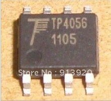
Original tp4056 NanJing Top Power chip.
This is the chip that HKJ tested & the ones I have. All pictures I’ve seen of boards that others have posted show this chip.
I have seen something almost like what you’ve thought of building before while i’ve been looking around and though that this might give you an idea
You can add voltmeters if you want as far as i can see.
I have that TP4056 boards with TP logo in chip. works fine
And board with no logo chip also works fine but they has interesting behavior
if input voltage below 5.0~5.1V, standby/full charge LED blink randomly. it doesn’t keep glowing.
if voltage over 5V, it works like chips with TP logo.
Alright, getting back into this charger build I’ve made a bit of an error.
I forgot about the little charge indicator lights on the tp4056 boards.
I need to somehow stretch the light about 11mm directly up through some black plastic. Any ideas on material, or some kind of glue or something that I could fill/cover the hole with to bring that indicator light to the surface?
Edit: The little volt meter arrived today. Neat little thing, definitely not to be relied on though. It only shows data to 1 decimal point. I’ll still use it just for kicks, maybe an occasional rough estimate. It’s going to be fun trying to fit it in the little single bay charger along with the 2 boards and the giant switch I chose.
It also reached a scorching 16* F in the work space today so I should be able to get back to working on mods in… about 4 months.
If you can find a piece of clear plastic, something that you can clearly see through, like a cassette tape case, you can cut that into the sizes you want for strips that will be clear in the center, with a junior hack saw is best, the long cut sides can be left rough and the top tip and bottom tip can be sanded flat, then you use a lighter to melt polish those surfaces on the two ends by lightly flowing the flame accross each end not constantly on them but very fast on-off, on-off until they look clear/seethrough, and that will make them clear/seethrough at each end like the center, it will be enough that it will give you a length of clear plastic in the middle that the led will beam light from the board to the other end giving you the extended light length you want.
I hope you understand that, i’d show you what i mean but i’m not at home, sorry about that.