Writeup of my modded L2D using one of Mattaus' silver-plated P60 dropins

After buying one of the sweet P60 dropins from Mattaus, I decided to build what I think is as close to my ideal EDC light as I can come up with. Most of my EDC items are in my briefcase, not in my pocket, so being super tiny isn’t a consideration – my EDC light just can’t be huge, and the L2D fits the bill rather well. I don’t have anything against tail switches, I just felt like this setup would be pretty cool if I could get it rigged up with a reliable switch.

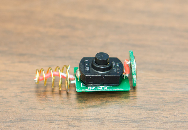
First off, I wasn’t crazy about the stock head, so I swapped it out for an L2T head with a flat stainless bezel. And swapped in a UCL from flashlightlens.com for the stock glass lens as well. I mocked this up once with the BLF17DD driver and it melted the stock switch’s innards in less than 10 minutes of use on high. So I tore it back down and replaced the stock switch with an Omten, replaced the stock spring on the battery side of the switch with the one in the pics (with a 22ga wire bypass), and rewired the contact on the dropin side of the switch. I also added a braided spring inside of the stock spring in the tailcap. The Omten switch doesn’t line up perfectly, but it works just fine with the little plastic plunger in the switch boot removed.

The dropin from Mattaus is a beast. Very heavy. The ground screw was a little tricky to wire up for me, but I got it done. Also added two blobs of solder on the spring side outer rim to help with grounding and to (hopefully) keep the spring side components from getting crushed when the head is tightened down.

The LEDs are dedomed XP-L V5 2A, dedomed in gas. Arctic Silver under the noctigon MCPCB, 20 or 22 ga wires on everything. Before changing the switch and modding the springs, it was pulling between 3 and 4 amps on high from a fresh Panasonic NCR18650PF… with the new switch and all the spring mods, it is now pulling a steady 6A on high from the same battery after about 20 seconds. The silver P60 dropin soaks up a whole bunch of heat. I ended up adding some foil tape to get it good and snug in the host, and heat transfer seems to be pretty good – once the dropin is saturated, it kicks the heat out to the outside of the head with a vengeance. So, I’m pretty pleased with the way it’s setup now – because of the dropin, the light can be run on high for several minutes before needing to worry about either the LEDs or my hands getting too hot.

Switch by itself

Completely disassembled

Driver & Foil

Switch alignment (sidebar, part of my L2D was glued together by solarforce - red stuff visible on threads. haters.)
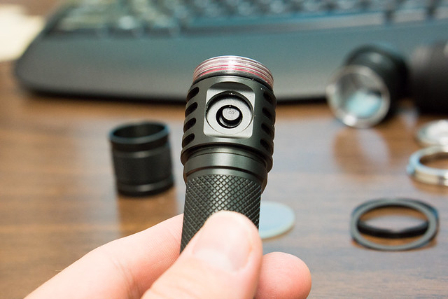
Assembled Side Shot

Front Shot

I wish I had a way to measure lumens or kcd output… but I don’t. Here are a handful of beamshots from my back yard. Unfortunately, I don’t really have any ‘normal’ lights to benchmark any of this, as nearly all of my lights are modified in some way or another and many are generally in pieces on my workbench until I decide I’ve perfected the light. And that doesn’t happen real often. So, I used three lights in the beamshots to hopefully convey some idea of what this thing looks like in person. The photos seem slightly underexposed on my monitor – in person the spill is wider for all three of these lights. Hotspot looks fairly accurate though.

Control Shot

L2M with dedomed XM-L2 U2 1A driven at about 3.8A, smooth reflector

Convoy S3 with 3-XPL V5 2A dedomed with standard Qlite at 3.04A

L2D with 3-XPL V5 2A dedomed driven at about 6A

All shots taken with Sony NEX-7 at 10mm (15mm full-frame equivalent), F4, 2.5 seconds, ISO 400, auto white balance. These are the first beamshots I’ve ever taken, so any pointers on taking better ones would be appreciated.

All in all, I’m not too crazy about the DD driver. It is brighter than my S3 with the same LEDs at 3.04A, but I don’t know that the additional brightness is going to be worth giving up a bunch of runtime. I’ll probably keep it the way it is for a few months and see at that point if I’d rather have it at 3A. Kinda curious what it would look like with a non-PWM driver. All that said, so far in messing around with it, the brightness on level 3 is more than enough for most tasks outdoors, and I like that the DD driver has a lower-low than what a 7135 driver can provide.

Nice mod, write up, and beam shots. You take better beam shots than I do. So I got no good tips for you on that. I can tell you a light meter can be had very cheap. If you just want one for you own comparative purposes, I recommend a HS1010a off ebay. The ones cabled sensor (see pic below) are my preference. If you want better, I check with RaceR86. He has done some work in that area and may have a recommendation for something better, but still budget.

Sure is a sharp looking light you built there.

How are you liking the tint of your dedomed XP-L V5 2A's? I know I will be buying some XP-L's specifically for dedoming eventually.

I dunno if I’ve just been lucky, but I’ve had pretty great success with the tint after dedoming the V5 2A’s. With the XM-L2’s I feel like about 50% had varying degrees of greenness when starting out with a cool white emitter. I have yet to have an XP-L 2A end up with an annoying amount of green tint shift after dedoming. I’ve done them in both gas and by prying off the dome when hot. I will say that the XM-L2’s (U2 1A) that I’ve dedomed via prying off the dome immediately after reflowing (aka, when it’s still hot and pliable right after the solder hardens) have either been neutral or still slightly cool after dedoming. Way less tint shift period doing it that way for me.

The XP-Ls seem to be somewhat more predictable — all the ones I’ve dedomed have been pretty darn similar in terms of before/after tint. I think I read in another thread here or on the ‘other’ place that there might be a small pocket of air/open space immediately above the phosphor, so when the dome comes off there isn’t a layer of silicone still on there (that I suppose would theoretically vary in thickness from one dedome to the next which would be an explanation for the tint shift lottery every time you dedome an XM-L2)… making the tint shift more regular from one dedome to the next. All in all, since the tint shift has been pretty consistent for me, I’ve been sticking to dedoming in gas just because it’s been relatively foolproof for me.

Out of about 25 or so XP-Ls that I’ve dedomed, I have killed two thus far… and I actually have no explanation at all as to how they died. They arrived as bare LEDs, reflowed onto 3-up noctigons in parallel, all three lit up when tested with 2xAA’s, then dedomed in gas and tested again with all three lighting up. Then weeks later when tested prior to going into a light one of the three didn’t light up (this has happened twice now). After pulling the ones not lighting up and testing by touching the leads from a 2xAA holder to the +/- pads on the bare LED, still nothing. Close inspection shows nothing looks out of the ordinary whatsoever - bond wires still intact (and generally still with silicone on them after the gas dedome), no black spots or any other weirdness. So take from that what you will. I haven’t been too concerned by it since two out of 25 ain’t that bad. Especially now that the price has finally started coming down.

I have modded a few L2d switches—The Omten switch works great—I find if you just build a complete new board it’s easier—that way you can slide the switch back a bit and solder the spring directly to the folded over long switch tap—This gives a better alignment with the boot—I still found resistance with that stock metal piece the drop in pos spring contacts-therefore I used a copper disc soldered direct to the other switch tap— A triple XPL using a fet with the stock plate ran around 5-6amps with the copper disc it pulls between 9-10 amps
It was a trial and error ordeal though

How’d you build a whole new board? I’m pretty interested in doing that. After using it for a few days, the misalignment is starting to get annoying. It works just fine the way it is, it’s just not perfect. It seems to be getting decent contact the way it is right now - pulling almost 7A at startup and settling down to right at 6A from an NCR18650PF, which is about all I want it to do.

I would like to get the switch lined up straight at some point though.

7amps from a PF that’s real good—I saw where you mentioned not sure if you wanted to keep the fet—mine has some really good lower modes .5 1.5 2.5 4 8.5-10 amps
I used a bread board from radio shack then just thermal epoxied the switch to it perfect thickness you just have to notch that black plastic shell a little bit for the folded tap—you know how the Omten has one long tab put it to the battery-I folded it tight against the switch before glueing I used the white plastic piece just grinded it a bit a little at a time
I wish I had pics seems like I would have some—I did 5 so far

Yeah honestly if I keep it, it’ll be because of the low modes. To the naked eye, I can’t tell a huge difference between this light at 6A and one of my convoys at 3A. It’s brighter for sure. Just not by a wide margin, which is what I was hoping for initially. Biggest difference to my eyes is the spill is brighter and it throws at tad farther - both side effects I’m sure of it kicking out like 800+ more lumens than the same LEDs at 3A. Basically 2A to each LED vs 1A to each LED. Just not as noticeable of a difference as I thought it would be. That said, it looks great for most uses on level 3 or 4 out of 5, and the low is much lower than any of my 7135-based drivers, which is relatively important for me. So I think I’ll keep it for a while like this. I do want to straighten up the switch though to get the light all the way ‘right’.

I too have a S2 with the triple XPLs It pulls 4.4amps on high lots of light but when I compare it to the P60 fet that pulls 8.5 + it’s like night and day—are you sure you’re getting 7amps to that module—might want to put that tail piece in the test loop—I actually took the L2D head apart and tested amperage at the module

May need to do that. It’s not holding steady at 7A — it’s like 6.8 right when it comes on and then settles down around 6.2 to 6.3 after about 20 seconds or so. That’s measuring at the tailcap, and obviously, the spring in the tailcap is awful. I have an additional braided spring set inside of the stock spring and soldered to the top of of it, so there’s ample contact for the juice to get through the spring(s) from the flashlight body to the back of the battery.

Still, it’s almost always worth testing at the LED itself to be sure. Also my DMM is super cheap. It’s modded with 14ga leads soldered in place to measure higher amps, but there’s still no telling how accurate it is. Only thing I’m sure of is it’s capable of reading high current… just no way to tell if the numbers it’s showing are anywhere near correct.

Bit late, but my suggested method is to cut the ground wire about 2 to 3 times longer than needed, then strip all but about 20mm off it. Twist it to stop the wire fraying, and then holding it against the loose screw, wrap it around the screw just under the head and then twist it in your fingers. Then solder the other end of the grounding wire to the driver. When it comes time to install the driver, simply use an allen key to screw the ground screw in. Provided you didn't twist too much it should free spin in the wire, and tighten right against the drop-in. That's how I do it anyway - perfect ground and simple to install :)